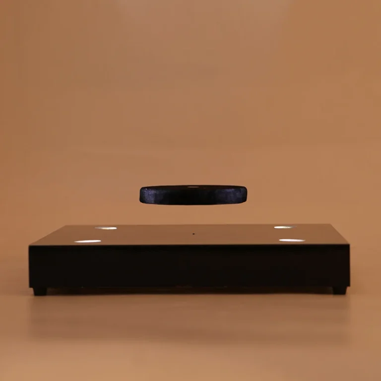
Belastbarkeit der Magnetschwebebahn: 7 Messkontrollen
Ein Lieferant kann eine Kilogrammzahl angeben und das Integrationsrisiko dennoch undefiniert lassen. magnetic levitation load capacity is a conditional result governed by mass, Schwerpunkt, versetzt, Lücke, Kontrollspanne, Störung, Laufzeit, und der sichere Zustand, der verwendet wird, wenn der deklarierte Grenzwert überschritten wird.
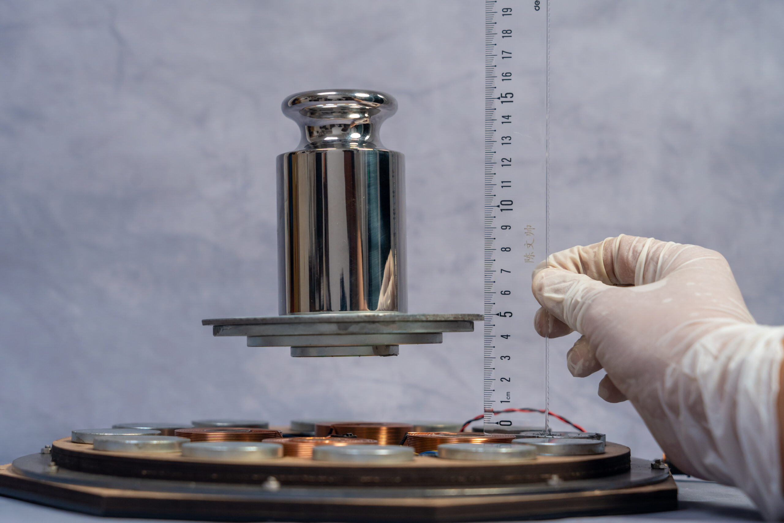
Was ist die magnetische Schwebelastkapazität in einer technischen Ausschreibung??
Load capacity is not a single number printed beside a module photograph. It is the payload that remains within the supplier’s defined stability and safety limits under a declared mechanical and electrical configuration.
The public Goodwell module page displays product-specific examples including 0–500 g, 0–1 kg, and 0–2 kg ranges with different levitation gaps. Those examples show why a buyer must match capacity to the exact module, Lücke, payload geometry, and test condition.
The correct RFQ therefore asks for both a mass limit and the conditions behind it. If the supplier provides only a nominal weight, the buyer cannot calculate off-axis moment, clearance, landing behavior, or the margin available during handling and operation.
| Field | Why it changes capacity | Required record |
|---|---|---|
| Mass | Sets the downward force | Calibrated payload value and tolerance |
| Center of gravity | Creates axial and radial moment | Position from magnetic axis |
| Offset | Consumes control margin | Maximum permitted eccentricity |
| Gap | Changes force and sensor range | Loaded gap and tolerance |
| Disturbance | Adds transient displacement | Berühren, vibration, Luftstrom, or rotation |
| Runtime | Exposes drift and temperature | Continuous duration and temperature |
Welche 7 Checks Make a Load Test Transferable?
Erste, measure the payload rather than relying on a catalogue description. Record the complete assembled object, including magnets, Empfänger, bracket, packaging element, and any decorative component that will remain during operation.
Zweite, locate the center of gravity in three dimensions. Dritte, record the offset from the magnetic axis, because a centered 500 g cylinder and an offset 500 g display can demand different radial correction and mechanical clearance.
Vierte, measure the loaded levitation gap from a fixed datum. Fünfte, define the disturbance that represents the real installation, such as a controlled touch, cabinet airflow, vibration, or repeated rotation.
Sechste, run the system after thermal stabilization for the intended operating duration. Seventh, define the acceptance and failure states, including maximum displacement, recovery behavior, controlled landing, surface contact, and whether the object can be safely reset.

How Should a Buyer Measure Load Capacity Before Integration?
Begin with a measurement fixture that fixes the base and identifies a repeatable reference plane. Add payload in controlled steps, record the gap and displacement, and stop when the declared acceptance condition is reached rather than when the object visibly falls.
At each step, record mass, Abmessungen, Schwerpunkt, versetzt, Lücke, Eingabebedingung, und Temperatur. A valid comparison requires the same measurement method across the load series, because changing the fixture or datum can create a false capacity increase.
Repeat the highest approved load after thermal stabilization and disturbance. For high-value retail objects, add the power-loss test because the load limit is incomplete if the system cannot bring the payload to a controlled supported state when power disappears.
- Use the complete assembled payload, not only the decorative shell
- Measure center of gravity and offset from the magnetic axis
- Record unloaded and loaded gap from a fixed datum
- Repeat at thermal stabilization and realistic disturbance
- State the acceptance limit and safe landing condition
- Keep the signed test record with the prototype approval file
How Do Public Goodwell Ranges Need to Be Interpreted?
Goodwell’s public module page lists several load and gap combinations, including high-gap configurations for lighter payloads and lower-gap configurations for heavier ranges. The page is useful for identifying possible hardware families, but it should not be read as a universal rating for an untested product geometry.
The company brief describes a customized industrial module range from 100 g to 2,000 g-plus and separately discusses a 2 kg floating display stand direction. Those figures require the exact module, structure, Schwerpunkt, Lücke, Laufzeit, and disturbance conditions before they can appear in a purchase specification.
For a new application, start with the Magnetic Levitation Module page, then compare the Product range Und Custom Case examples. Send the payload drawing and measurement assumptions through Kontakt / Freie Gestaltung before selecting a production configuration.
Checkliste für Lieferantenaudits: 5 Vor der Unterzeichnung anzufordernde Dokumente
- Load-capacity test report: identifies module, Nutzlast, Schwerpunkt, versetzt, Lücke, input, Laufzeit, and acceptance result.
- Calibration or measurement record: states the weighing device, datum, resolution, and measurement uncertainty or tolerance used.
- Disturbance validation report: documents touch, vibration, Luftstrom, Drehung, and recovery limits relevant to the installation.
- Konfigurationsdatenblatt: separates product-specific ranges from general module families and identifies safe operating limits.
- Prüfmuster vor dem Versand: proves that payload, Lücke, Stabilität, and landing checks are repeated on production units.
FAQ: Belastbarkeit der Magnetschwebebahn
Q: What does magnetic levitation load capacity mean?
It is the maximum declared payload that a specified module can support under defined geometry, Lücke, Schwerpunkt, Störung, Laufzeit, and safety conditions. A mass value without those conditions is not a transferable engineering rating.
Q: Is a 2 kg rating valid for every magnetic levitation module?
NEIN. Der 2 kg figure in the Goodwell brief is associated with a specific floating display stand direction and must not be generalized to every module. Request a test record matching the exact structure, Schwerpunkt, Lücke, Laufzeit, and disturbance condition.
Q: Why is center of gravity important when measuring payload?
Center of gravity determines the moment applied around the magnetic axis, not only the downward force. Two objects with the same mass can require different control margins when one has a larger offset or a taller, uneven shape.
Q: How should a supplier report a load-capacity test?
The report should identify module revision, payload mass and dimensions, Schwerpunkt, versetzt, Lücke, power condition, Temperatur, Laufzeit, Störung, and acceptance criteria. It should also state whether the test ended in stable levitation, controlled landing, or failure.
If your object has an offset center of gravity, rotating requirement, or high-value retail presentation, send the drawing and payload data to Goodwell Free Design. E-Mail [email protected] with mass, Abmessungen, Schwerpunkt, Lücke, Laufzeit, and disturbance conditions.
For a physics reference on forces and measurement concepts, konsultieren OpenStax-Physik. The reference supports the underlying scientific context, while the actual capacity decision requires a configuration-specific supplier test.