전자기 부상 모듈이 어떻게 작동하고 자신의 구축을위한 단계

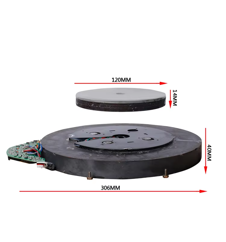
An electromagnetic levitation module lets you float small objects in midair using the force from a controlled electromagnet. You use sensors to detect the position of the object, then a control circuit adjusts the magnetic force to keep it steady. Many industries use this technology.
You can find it in transportation systems and wireless charging devices.
Researchers use it for 3D metal printing and to build tiny robots for medical tasks.
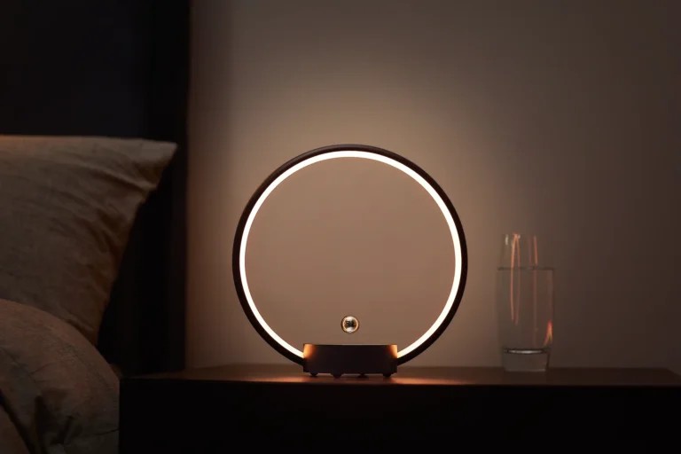
Everyday products like levitating globes and bonsai trees also use this system.
With basic tools and patience, you can explore this fascinating technology and build your own.
주요 시사점
Electromagnetic levitation uses magnetic forces and sensors to float objects without physical support by balancing magnetic repulsion against gravity.
Building a levitation module requires key parts like a copper wire coil, steel core, Hall effect sensors, a microcontroller, and a stable power supply.
Precise sensor placement and a responsive control circuit keep the floating object steady by constantly adjusting the magnetic field.
Careful assembly, wiring, and regular calibration improve stability and help you fine-tune the levitation height and performance.
Follow safety guidelines, avoid touching powered coils, and watch for overheating to build a safe and reliable levitation module.
작동 방식
Magnetic Levitation Principle
You can make objects float using magnetic forces. The electromagnetic levitation module relies on the repulsive force between like magnetic poles. When you adjust the strength and direction of this force, you balance it against gravity. If you match the magnetic force to the weight of the object, the object stays suspended in the air. This happens because identical magnetic poles push away from each other. You control the magnetic field so the repulsive force holds the object up. This principle lets you levitate objects without any physical support.
팁: Always check the alignment of your magnets. Proper alignment helps you achieve stable levitation.
The strength of the magnetic field affects how high you can levitate an object. You can see the relationship in the table below:
Aspect | Explanation | Effect on Levitation Height |
|---|---|---|
Halbach Array Effect | Using a Halbach array nearly doubles magnetic field strength and more than triples lift force due to stronger eddy currents. | Increased magnetic field strength significantly raises levitation height by increasing lift force. |
Eddy Currents | Stronger magnetic fields induce stronger eddy currents in conductive materials, which generate opposing magnetic fields that repel the object. | Greater magnetic field strength leads to stronger repulsive forces, increasing levitation height. |
Diamagnetic Force Relation | Magnetic force on diamagnetic materials is proportional to the gradient of the square of the magnetic field (∇(B·B)). | Stronger magnetic fields produce greater repulsive forces that can counteract gravity, raising levitation height. |
Stability and Control | Stable levitation requires feedback control systems that dynamically adjust magnetic field strength to maintain a constant gap. | Magnetic field strength must be managed dynamically to sustain and control levitation height. |
Sensors and Feedback Loop
You need sensors to detect the position of the floating object. The most effective sensors include optical incremental sensor grids, analog Hall sensor arrays, and encoder sensors. Optical incremental sensor grids can measure movement with nanometer precision. Analog Hall sensor arrays help you find the exact position and provide reliable readings. Incremental and absolute encoders track the object’s location and movement. Some advanced systems use tunnel magneto resistance (TMR) sensors, which work well in challenging environments and offer accurate position detection.
You place these sensors near the floating object. The sensors send signals to the control circuit. The circuit uses this information to adjust the magnetic field. This feedback loop keeps the object steady and prevents it from falling or wobbling.
메모: Accurate sensor placement improves stability and makes the levitation smoother.
Control Circuit Basics
You use a control circuit to manage the magnetic field. The circuit receives data from the sensors. It calculates how much magnetic force you need to keep the object floating. The control circuit changes the current in the electromagnet coil. This adjustment increases or decreases the magnetic field strength.
You can build a simple control circuit using a microcontroller, such as an Arduino. The microcontroller reads sensor data and sends signals to a power transistor or driver circuit. This setup lets you control the electromagnet in real time. You can program the microcontroller to respond quickly to changes in position. Fast response helps you maintain stable levitation.
If you want to experiment, try changing the control algorithm. Different algorithms can improve stability or allow you to levitate heavier objects.
You combine the magnetic levitation principle, precise sensors, and a responsive control circuit to create a working electromagnetic levitation module. Each part plays a key role in keeping the object floating and stable.
Electromagnetic Levitation Module Components

Building your own electromagnetic levitation module starts with gathering the right parts. Each component plays a key role in making the system work smoothly and safely.
Electromagnet Coil and Core
You need a strong electromagnet to lift objects. Most coils use copper wire because it conducts electricity well. You wind the wire around a steel shaft, which acts as the core. Steel becomes a temporary magnet when current flows through the coil. This setup lets you create a powerful magnetic field.
Magnet wire: Use 26 또는 27 gauge copper wire for best results.
Core: Choose a steel shaft for the core.
Frame: Build a sturdy frame to hold the coil and core in place.
팁: Make sure the coil and core are tightly wound and aligned. This helps you achieve stable levitation.
Sensors and Microcontroller
Sensors help you detect the position of the floating object. Hall effect sensors work well because they are thin, 유연한, and provide accurate readings in small spaces. You can use the A3144 Hall effect sensor for reliable performance.
Microcontrollers process sensor data and control the electromagnet. You might use an Arduino, MSP430, or even an FPGA board. These controllers read signals from the sensor and adjust the coil current to keep the object floating.
Component | Specification/Model | Quantity |
|---|---|---|
Hall Effect Sensor | A3144 | 1 |
MOSFET Transistor | Irfz44N | 1 |
Resistors | 330 옴, 1k ohm | 1 each |
Indicating LED | 5mm (any color) | 1 |
Diode | IN4007 | 1 |
Magnet Wire | 26 또는 27 Gauge | 1 kg |
Vero Board | Small size | 1 |
Power Supply and Safety
You need a stable power supply for your electromagnetic levitation module. For small projects, a 5V or 12V DC supply rated at 1A works well. Always match the power supply to your coil’s resistance and current needs.
Heat can build up in the coil, so you should watch for overheating. Some modules use temperature sensors to shut off power if things get too hot. Keep good airflow around your device and use foam padding to protect the base.
Safety Alert: Never touch the coil when it is powered. Wait for it to cool down before making adjustments.
Assembly
Building your own electromagnetic levitation module can be a rewarding project. You will learn how to prepare the parts, build the circuit, and place the sensors for the best results. Follow these steps to assemble your device and achieve stable levitation.
Preparing Parts
Start by gathering all the necessary components. You will need:
Copper wire (0.3–0.4 mm diameter)
Steel core or shaft
Cardboard or plastic for the frame
Hall effect sensor (A3144)
IRFZ44N transistor
HER207 diode
Resistors (220 Ω, 330 Ω, 1 kΩ)
LED (optional for indication)
5V power supply
Neodymium magnets
Soldering tools and glue
Step-by-step preparation:
Build a frame for the electromagnet. Use cardboard or plastic. Make sure the frame fits the core and allows for easy winding.
Wind ~에 대한 550 turns of copper wire tightly around the frame. Keep the layers even. This helps the coil work efficiently.
Solder the ends of the coil wire. Leave enough length to connect to the circuit later.
Prepare the Hall effect sensor. Check the datasheet for the correct orientation.
Gather the other electronic parts. Lay them out on your workspace for easy access.
팁: Use a small piece of tape to hold the first turn of wire in place. This keeps the coil neat as you wind.
Building the Circuit
Now you will connect the electronic components to control the electromagnet.
Place the Hall effect sensor inside the coil. Secure it so it does not move.
Solder the sensor leads to the circuit board. Connect the output to the microcontroller input.
Connect the coil to the IRFZ44N transistor. The transistor acts as a switch for the electromagnet.
Add the HER207 diode in parallel with the coil. This protects the circuit from voltage spikes.
Insert resistors where needed. 예를 들어, use a 220 Ω resistor with the LED if you want a power indicator.
Connect the power supply. Use a 5V supply to prevent overheating.
Attach the neodymium magnet to the object you want to levitate. Make sure the magnet’s poles face the right direction for repulsion.
You can use a breadboard for testing or solder the parts onto a vero board for a permanent build. Some hobbyists use modular kits that include pre-wound coils and sensor mounts. These kits make assembly faster and allow for easy upgrades.
메모: Always double-check your wiring before powering the circuit. Incorrect connections can damage components.
Sensor Placement
Sensor placement is critical for stable levitation. The Hall effect sensor must sit directly below the electromagnet and above the levitating object. This position lets the sensor detect small changes in the magnetic field as the object moves.
Align the electromagnet, sensor, and object along the same vertical axis.
Use a ruler or guide to keep everything centered.
If you use multiple sensors, arrange them to detect movement in all directions.
Proper alignment helps the control circuit respond quickly to any shifts. When the levitated object tips or moves off-center, the sensor detects the change. The circuit then adjusts the electromagnet to bring the object back to the center. If you misalign the parts, the system cannot correct the object’s position, and it may fall.
⚠️ Alignment Alert: Take your time with alignment. Even a small shift can cause instability.
You can customize your electromagnetic levitation module by using different frame materials or adding extra sensors. Some builders use 3D-printed cases for a professional look. Others experiment with sensor types or magnet shapes to improve performance.
Customization Idea: Try using a potentiometer to adjust the coil current. This lets you fine-tune the levitation height.
With careful assembly and precise alignment, you can achieve smooth and stable levitation. Take notes during your build. Small adjustments can make a big difference in performance.
Wiring & Calibration
Wiring Steps
You need to connect each part of your electromagnetic levitation module carefully. Start by wiring the Hall effect sensor to the microcontroller. Connect the sensor’s output pin to the analog input on your board. Attach the coil to the transistor, and then link the transistor to the microcontroller’s digital output. Place the diode across the coil terminals to protect your circuit from voltage spikes. Use a breadboard for testing before soldering everything onto a permanent board.
팁: Double-check each connection before turning on the power. A small mistake can damage your components.
Sensor Adjustment
You can improve the accuracy of your module by adjusting the sensor’s sensitivity. One common method uses a potentiometer as a voltage divider. By turning the potentiometer, you set the reference voltage for the comparator circuit. This lets you fine-tune how the Hall effect sensor responds to the magnetic field. Some advanced systems use a voltage shifter with accelerometers. This shifts the sensor’s output voltage to fit the measurement range, making the sensor more sensitive to small changes.
Place sensors close to the floating object for better readings.
Use more than one sensor to get data from different angles.
Combine sensor data to reduce errors from noise or interference.
Accurate sensor placement and adjustment help your module detect the object’s position more reliably.
Calibration and Tuning
You must calibrate your electromagnetic levitation module for stable performance. Start by measuring the floating distance with a Hall-effect-based distance sensor. Adjust the proportional gain (P gain) in your control algorithm to keep the object steady. Try to optimize the resistance coefficient to reduce energy loss and improve stability. Environmental factors like temperature and humidity can affect your results, so check your module in different conditions.
You can use a small Hall effect sensor to measure the magnetic field strength during tuning. Most modules work at high frequencies, so quick adjustments help maintain stability. Advanced calibration may use neural networks or linearization techniques to handle system nonlinearity.
Calibration is not a one-time task. Test and adjust your module regularly for the best results.
Troubleshooting
Common Issues
You may face several challenges when operating your electromagnetic levitation module. Achieving stable levitation can be tricky because the system reacts strongly to even small changes. The magnetic force does not increase in a straight line as you move the object, so the balance point is very sensitive. You might notice the object overshoots its position or takes too long to settle. 때때로, the module responds slowly or becomes unstable if there is noise in the sensor signals. Unknown disturbances, like a sudden bump or a change in room temperature, can also cause the object to fall. The system may not adjust itself automatically, so you need to tune it by hand.
Electromagnetic interference (EMI) can also cause problems. EMI often comes from the electromagnet, the motor, or even sparks in the circuit. This interference can disrupt your sensors and control electronics, making it hard to keep the object floating. More windings on your coil can increase EMI, so you need to balance strength and stability.
팁: If your object wobbles or drops, check for sensor noise, loose wires, or nearby devices that might cause interference.
Final Adjustments
You can improve stability after your first setup by making a few key adjustments:
Use a trimmer or potentiometer to set the best hover point for your object.
Average several sensor readings to reduce noise and get more accurate data.
Replace the flyback diode with two white LEDs and a resistor to limit unwanted currents.
Power your Hall sensor with a steady 3.3V supply for consistent output.
Place adjustment parts where you can reach them easily, but keep them secure to avoid movement.
For final testing, turn your module on and off several times to see if it works every time. Let it run for a while to check for overheating. Test other electronics nearby to make sure the magnetic field does not affect them. Try levitating your object with different barriers, like thin plastic sheets, to see how the system responds.
Safety Tips
Always follow safety guidelines when working with electromagnetic levitation modules. Keep the temperature stable around your device, as heat can affect performance. Watch for strong winds or sudden movements that might knock the object out of place. Make sure all parts are secure and cannot move during operation. Limit the levitation gap to prevent the object from touching the coil or frame. Design your control system to avoid sudden jumps or errors. Careful setup and regular checks help you keep your module safe and reliable.
You can build your own electromagnetic levitation module with patience and basic tools. Many beginners succeed because:
You only need simple hardware and standard parts.
Relay coils and Hall sensors are easy to find.
Clear instructions and troubleshooting tips guide you.
You can calibrate the circuit with a trimmer and check sensor orientation.
When you build and test your module, you learn how sensors, magnets, and control systems work together. These projects help you understand 자기부상, 피드백 제어, and system design. Try new ideas, stay safe, and share your results or questions in the comments!
자주하는 질문
How much weight can an electromagnetic levitation module lift?
The weight you can lift depends on your coil strength, magnet size, and power supply. Most DIY modules can levitate objects weighing up to 50 그램. For heavier objects, you need a larger coil and a stronger power source.
Can you use any type of magnet for levitation?
You should use neodymium magnets. These magnets are strong and small. Other magnets, like ceramic ones, do not provide enough force for stable levitation. Always check the magnet’s polarity before starting your project.
Why does my object keep falling instead of levitating?
Your object may fall if the sensor is misaligned or the coil current is too low. Check your wiring and sensor placement. Make sure the control circuit responds quickly to changes in position.
Is electromagnetic levitation safe for kids to try?
You can build a simple module safely with adult supervision. Always avoid touching the coil when powered. Use low-voltage supplies and keep magnets away from electronics and small children.
Do you need to program the microcontroller?
예, you need to upload code to the microcontroller. The code reads sensor data and adjusts the coil current. You can find sample code for Arduino online.
팁: Start with basic code and test your setup before making changes.


