Magnetic Levitation Prototype Checklist for OEM/ODM Projects
Engineering a new floating consumer device or retail display requires a structured magnetic levitation prototype checklist before committing capital to production tooling. Without strict prototyping validation gates, hardware teams often face unexpected thermal throttling, sensor drift, and catastrophic drop damage during field operation.
Our engineering team at Goodwell evaluates custom OEM and ODM projects through a phased validation workflow. This technical guide outlines essential testing milestones required to transition an experimental levitation concept into a stable, production-ready commercial hardware platform.
1. Defining Input Specifications: Масса, Center of Gravity, and Gap
Every successful prototype begins with rigorous mechanical boundary definition. Under calibrated static load conditions across a 100 г к 2,000 g payload range, vertical levitation gap must maintain 12 к 20 mm baseline stability before exterior tooling release.
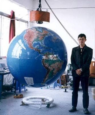
Engineers must calculate both the total floating mass and the vertical center of gravity offset. If the center of mass exceeds specified radial limits, the restorative electromagnetic torque decreases, causing uncontrolled wobbling or permanent radial instability.
| Prototype Phase | Test Condition | Engineering Parameter | Acceptance Baseline |
|---|---|---|---|
| Stage 1: Mechanical | Static calibrated mass on floating armature | Center of gravity vertical offset (Z-axis) | < 15 mm above floating magnet plane |
| Stage 2: Electromagnetic | Closed-loop coil excitation at 25°C | Restorative radial stiffness (N/mm) | > 2.5 N/mm radial deviation resistance |
| Stage 3: Термальный | Continuous 24-hour operation at rated load | Coil assembly surface temperature rise | < 30°C rise over ambient baseline |
| Stage 4: Power-Loss | Sudden AC input line cutoff at peak height | Docking capture speed and orientation | 100% capture without base rebound |
| Stage 5: Packaging | ISTA-1A transit simulation (drop & vibe) | Module core structural integrity | Zero displacement of Hall sensor arrays |
2. Thermal Management and Continuous Coil Drive Stability
Electromagnetic drive coils generate continuous Joule heating during active levitation. In continuous 24-hour drive tests at 25°C ambient temperature, electromagnetic coil surface temperature rise must remain within verified thermal limits to prevent sensor drift and efficiency degradation.
Excessive internal base temperatures alter the magnetic permeability of core materials and introduce thermal offsets into linear Hall effect sensors. Prototyping enclosures must incorporate passive heat dissipation pathways or aluminum thermal heat spreaders to safeguard control loop accuracy.
3. Power-Loss Fail-Safe and Safe Landing Verification
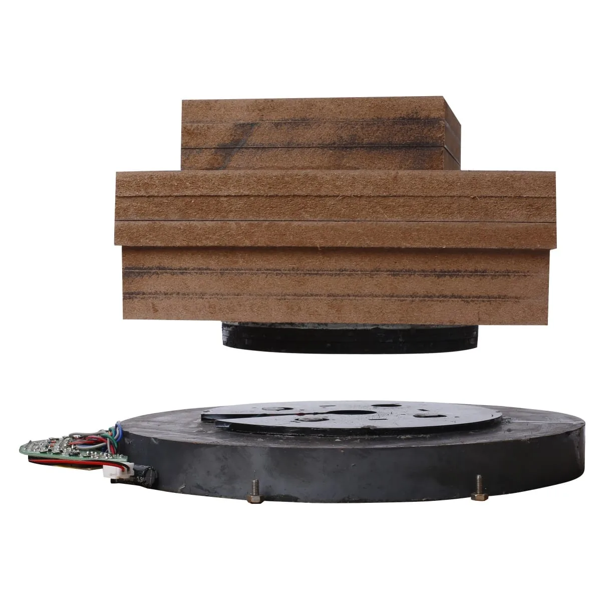
Sudden utility power interruptions represent the most critical operational hazard for floating displays and lamps. During simulated sudden grid disconnection under full rated payload, the emergency landing mechanism must guide the floating core to secure base docking to be validated by drop testing.
A robust bottom-push architecture utilizes permanent magnetic attraction bias to pull the floating object safely downward onto designated damping pads within milliseconds. Without this fail-safe mechanism, the suspended payload will tumble laterally and suffer impact damage.
4. Fundamental Physics Behind Dynamic Levitation Equilibrium
Achieving stable magnetic suspension requires overcoming Earnshaw’s theorem through high-speed feedback control. As detailed in the OpenStax Physics Principles and Applications textbook, static magnetic fields cannot maintain three-dimensional stability without active electromagnetic modulation.
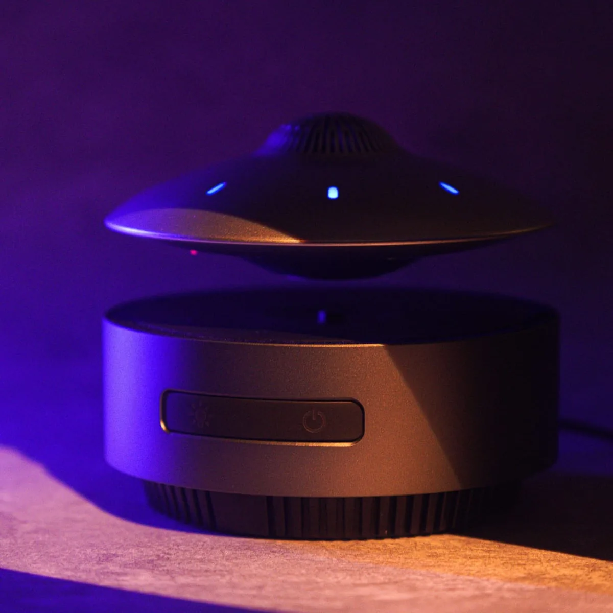
Our standardized модуль магнитной левитации systems utilize high-frequency pulse-width modulation driver circuits that adjust coil currents thousands of times per second. This closed-loop control guarantees instantaneous corrective force whenever external air currents perturb the floating object.
5. OEM/ODM Prototype Development Workflow at Goodwell
С более чем 30 years of manufacturing experience according to our public company profile, Goodwell operates a 27,000 m² factory facility holding 100+ патенты. We provide comprehensive custom OEM and ODM case solutions backed by complimentary engineering design support.
Our engineering team works closely with B2B buyers from initial CAD envelope modeling through rapid 3D-printed proof-of-concept testing. All proprietary designs undergo strict intellectual property safeguards and patent and certificate validation prior to mass production tooling kick-off.
6. Supplier Audit Checklist for Prototype Milestone Approvals
- Mechanical Clearance Verification: Review 3D CAD files for a minimum 5 mm internal radial housing clearance around driver coil envelopes.
- Center of Gravity Validation: Obtain physical prototype balancing reports demonstrating payload stability under dynamic rotation.
- Thermal Endurance Log: Demand continuous 24-hour temperature telemetry showing driver PCB temperatures below critical component ratings.
- Power-Loss Safety Testing: Verify 100 consecutive AC disconnect cycles with zero lateral ejection or exterior housing fracture.
- Wireless Power Coupling Audit: For illuminated products, confirm receiver coil resonance alignment under ±3 mm axial displacement.
7. Часто задаваемые вопросы (Часто задаваемые вопросы)
вопрос: What is the typical lead time for a custom magnetic levitation prototype? А: Functional prototypes utilizing standard module cores require 7 к 10 business days. Fully custom enclosures and tailored driver boards take 20 к 30 дни.
вопрос: How do you verify the center of gravity on an irregular floating object? А: We utilize precision multi-axis balancing rigs and 3D CAD mass simulations. Counterweights are strategically integrated to align the center of gravity directly along the central magnetic axis.
вопрос: What input parameters should our engineering team provide for Free Design evaluation? А: Your team should provide target payload mass, physical dimensions, необходимый зазор для левитации, and operating power constraints. Our engineers will perform preliminary feasibility simulations.
вопрос: Can the prototype include wireless induction powering for internal LEDs? А: Да, our bottom-push architecture integrates high-frequency wireless resonant induction coils that transmit power across the air gap. This delivers constant illumination without internal batteries.
Initiate Your Maglev Prototype Development
Are you developing a proprietary floating product or an interactive retail display? Submit your project parameters to our engineering desk at [email protected] or connect with our technical specialists via WhatsApp at +86 134 5018 0012. Explore our full engineering capabilities on our Goodwell Contact and Free Design Portal.