
Bottom Push Magnetic Levitation System: How It Works and What to Specify
Bottom Push Magnetic Levitation System: How It Works and What to Specify
A bottom push magnetic levitation system looks like a simple trick until you try to hold a payload stable under real-world disturbance. The object floats above the base, the base generates the field, and the engineering that keeps that object centered, level and safe is where most product development fails. This guide explains how the bottom-push architecture works, what its limits are, and what to put in your RFQ before you commit.
How a Bottom-Push Levitation System Works
In a bottom-push design, the levitating object carries a magnet assembly and the base contains the electromagnet coils and position sensors. The coils push upward against the magnet in the payload, and a closed-loop controller adjusts coil current to hold the payload at a set levitation gap. The system actively balances the payload against gravity and disturbance, which is why it is called a levitation system rather than a magnetic holder.
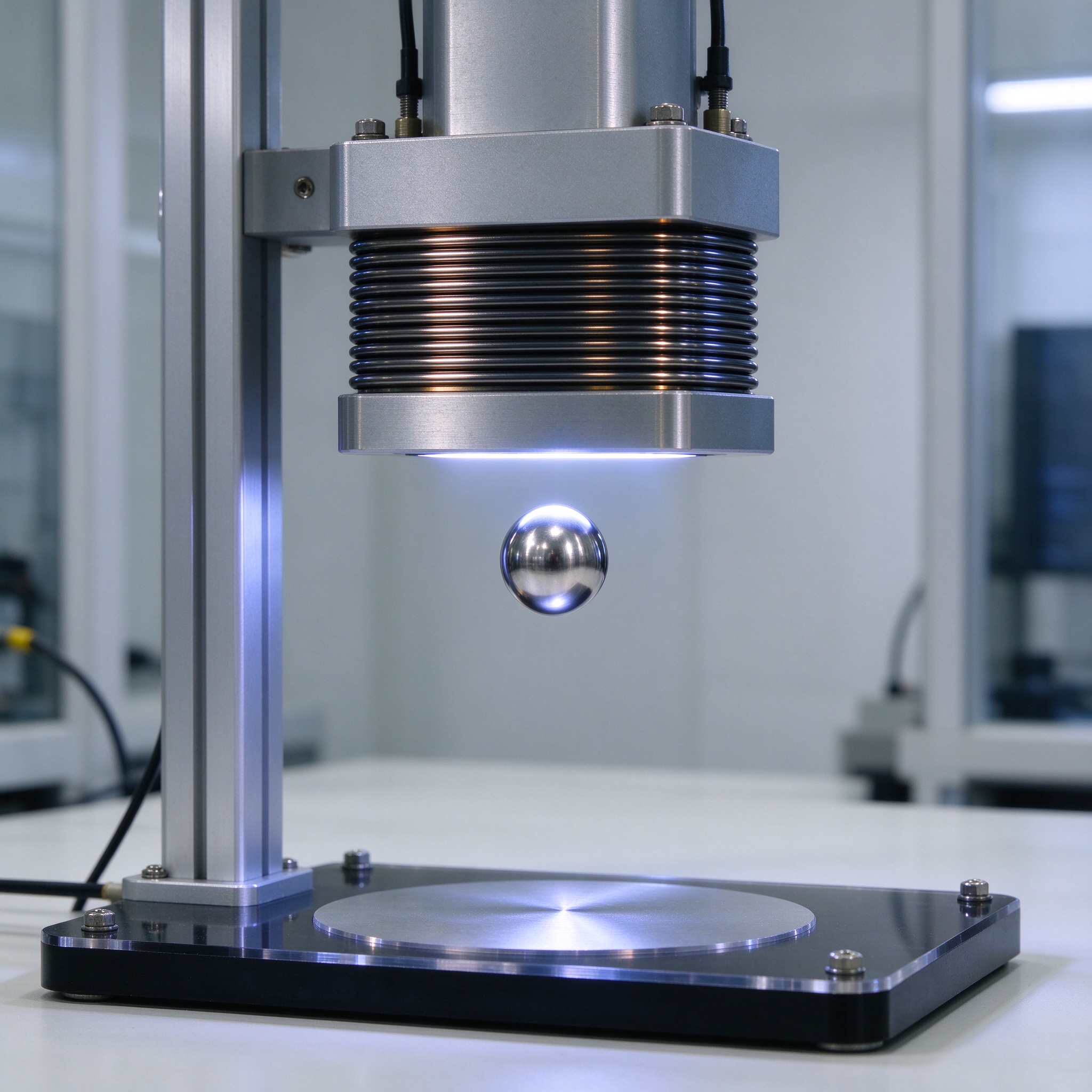
The object itself is passive in the electrical sense: it carries permanent magnets but no power source, so the architecture suits products such as floating lamps, speakers and display items where wiring through the payload is impossible. The active electronics, the control loop and the power management all live in the base, which is also where failure modes concentrate.
The Closed-Loop Control That Keeps It Stable
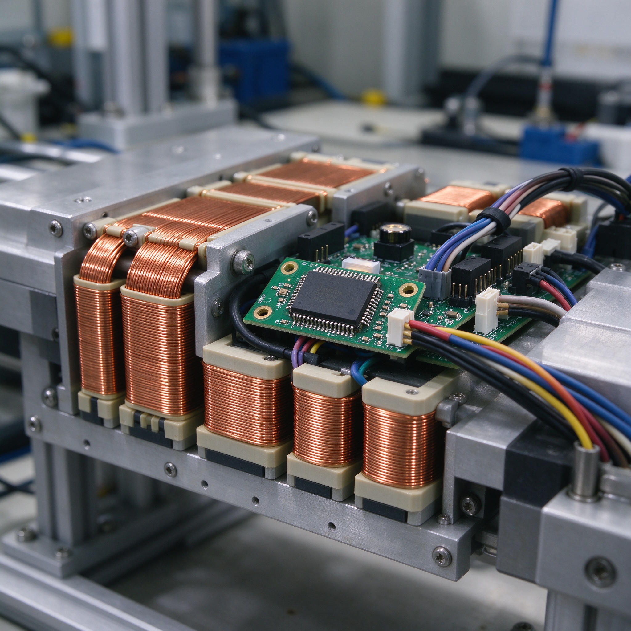
Position sensors measure the gap between the payload and the base dozens or hundreds of times per second, and the controller converts that measurement into coil current. The control law has to reject two kinds of disturbance: static ones such as a slightly off-center center of gravity, and dynamic ones such as air movement, vibration or a finger pushing the payload sideways.
The engineering distinction between a toy and a product-grade system is the control algorithm and its tuning. A bottom-push magnetic levitation system with proportional-integral-derivative (PID) control can hold a payload steady in still conditions, but load, ギャップ, coil temperature and external force all change the plant, so the controller must be robust across the operating envelope, not just at the demo point.
Axial and Radial Stability Are Different Problems
The bottom-push configuration controls vertical position directly, but radial stability, keeping the payload from drifting sideways, is a separate loop. The payload must stay centered above the coil assembly, and any lateral displacement has to be corrected without destabilizing the vertical loop. That coupling is the part of the design that most integration failures come from.
When you specify a module, the load and the center of gravity define how hard the radial loop has to work. A tall object with its mass high above the magnets creates a pendulum effect that demands faster and stronger correction than a compact, low-center-of-gravity payload, so the same module can feel rock solid with one product and shaky with another.
What Limits the Load and the Gap
Load capacity and levitation gap trade off against each other. The gap defines how much vertical travel the control loop must manage, and the coil assembly defines how much force it can generate. Increasing either the gap or the payload mass pushes the system closer to its control limit, where disturbances that would be trivial at a small gap become stability risks.
The published load figure is never the whole story. A module rated for a specific mass is rated at a stated center of gravity, a stated gap and stated environmental conditions; change any of them and the practical capacity changes. That is why our engineering team asks for the payload geometry and weight distribution, not just the gram weight, before quoting a module.
Power Loss Protection: What Happens When the Power Drops
The first question every buyer asks is what happens when the power goes out. In a bottom-push system, the payload has no mechanical support, so a sudden power loss means the object falls unless the controller detects the loss and acts within milliseconds. The protection design must detect the failure, arrest the payload’s fall and land it safely on the base or a receiver.
A properly designed power-loss protection system is designed to prevent free-fall damage under its specified operating conditions: detection latency, 積載質量, gap and landing structure all have to be validated together. When you audit a supplier, request the power-loss test record with the test conditions stated, and treat any unqualified claim of zero damage as marketing until the record is produced.
Wireless Powering for Floating Products
Many bottom-push levitation products also need power in the payload: a lamp needs to light, a speaker needs to play. Wireless induction powering delivers that through electromagnetic coupling between a coil in the base and a receiver coil in the payload, which is what allows floating lamps and speakers to run without batteries or wires.
The coupling efficiency, the alignment tolerance and the heat generated in both coils are design variables that affect the product’s continuous-operation performance. A product that lights beautifully for five minutes and overheats after an hour has a wireless-power problem, not a levitation problem, so the thermal and power budgets belong in the same specification as the levitation parameters.
What to Put in Your RFQ for a Bottom-Push Levitation Module
A vague RFQ produces vague quotations. State the payload mass and geometry, the target levitation gap, the required stability under the disturbances your environment produces, the power-loss behavior you expect and the operating duty cycle. State whether wireless power is required and the power budget for the payload.
Ask for the test records that back each parameter: load capacity measured at the stated center of gravity, gap range with the control margin, power-loss test with detection latency, and continuous-operation temperature data. A supplier who can produce these records is selling an engineered system; one who cannot is selling a prototype.
サプライヤー監査チェックリスト: 6 Questions Before You Commit
Before you place an order for a bottom push magnetic levitation system, verify these six items. Each one protects a different part of your product’s reliability:
- 1. Load capacity test record stating the center of gravity, gap and test conditions used.
- 2. Stability test data under defined disturbances, including the correction response time.
- 3. Power-loss protection test with detection latency and the landing behavior recorded.
- 4. Wireless power coupling efficiency and thermal data for your payload power budget.
- 5. Continuous-operation endurance data at your intended duty cycle.
- 6. Sample validation process, lead time and the integration documentation included.
Working through this checklist before you sign removes most of the risk that shows up later in product development, when changes are expensive. Each document maps to a specific reliability claim you can hold the supplier to.
よくある質問: Bottom Push Magnetic Levitation System
How does a bottom push magnetic levitation system keep an object floating?
Electromagnet coils in the base push against permanent magnets in the payload, and a closed-loop controller adjusts coil current based on position sensor readings to hold the payload at a set gap, rejecting disturbances continuously.
What is the maximum load a bottom-push module can lift?
Load depends on module size, ギャップ, center of gravity and environment; typical modules support from around 100 g up to 2,000 g and beyond with custom design. The rated load is only valid at the stated center of gravity and gap, so verify those with the supplier.
What happens to the floating object when power fails?
In a designed system, the controller detects the power loss and lands the payload safely on the base within milliseconds, preventing free-fall damage under the specified conditions. Request the power-loss test record with its test conditions rather than relying on claims.
Can the floating product be powered without batteries or wires?
はい, with wireless induction powering: a coil in the base couples energy to a receiver coil in the payload, powering lamps, speakers and other electronics without wires. Coupling efficiency and thermal management are part of the design.
Why does my product wobble when it should float?
Wobble usually means the control loop is not matched to the payload’s weight distribution, the gap is outside the module’s stable range, or the disturbance exceeds the correction authority. Verify the center of gravity and the required gap with the module supplier before integration.
CTA
Developing a product around a bottom push magnetic levitation system and need the module specified against your payload? Send us your payload mass, geometry and target gap, and our engineering team will confirm the module, the test records and a sample program.
Refer to the Goodwell Maglev Module overview for the module families and integration options available.