
PID Control Magnetic Levitation: Tuning, Stability and What to Specify
PID Control Magnetic Levitation: Tuning, Stability and What to Specify
PID control magnetic levitation is the workhorse of stable suspension, but the phrase covers a wide range of implementations, from hobby demonstrations to industrial modules that hold payloads steady for years. This guide explains what PID control does in a magnetic levitation system, why tuning matters more than the algorithm name, and what a buyer should verify before integrating a module.
Why PID Control Is the Standard for Magnetic Levitation
Magnetic levitation is inherently unstable: without active correction, the payload either falls or is pulled into the coils. Proportional-integral-derivative (ПИД) control is the standard way to add that correction because it combines three behaviors: proportional response to the current error, integral action that removes steady-state offset, and derivative action that anticipates the payload’s velocity.
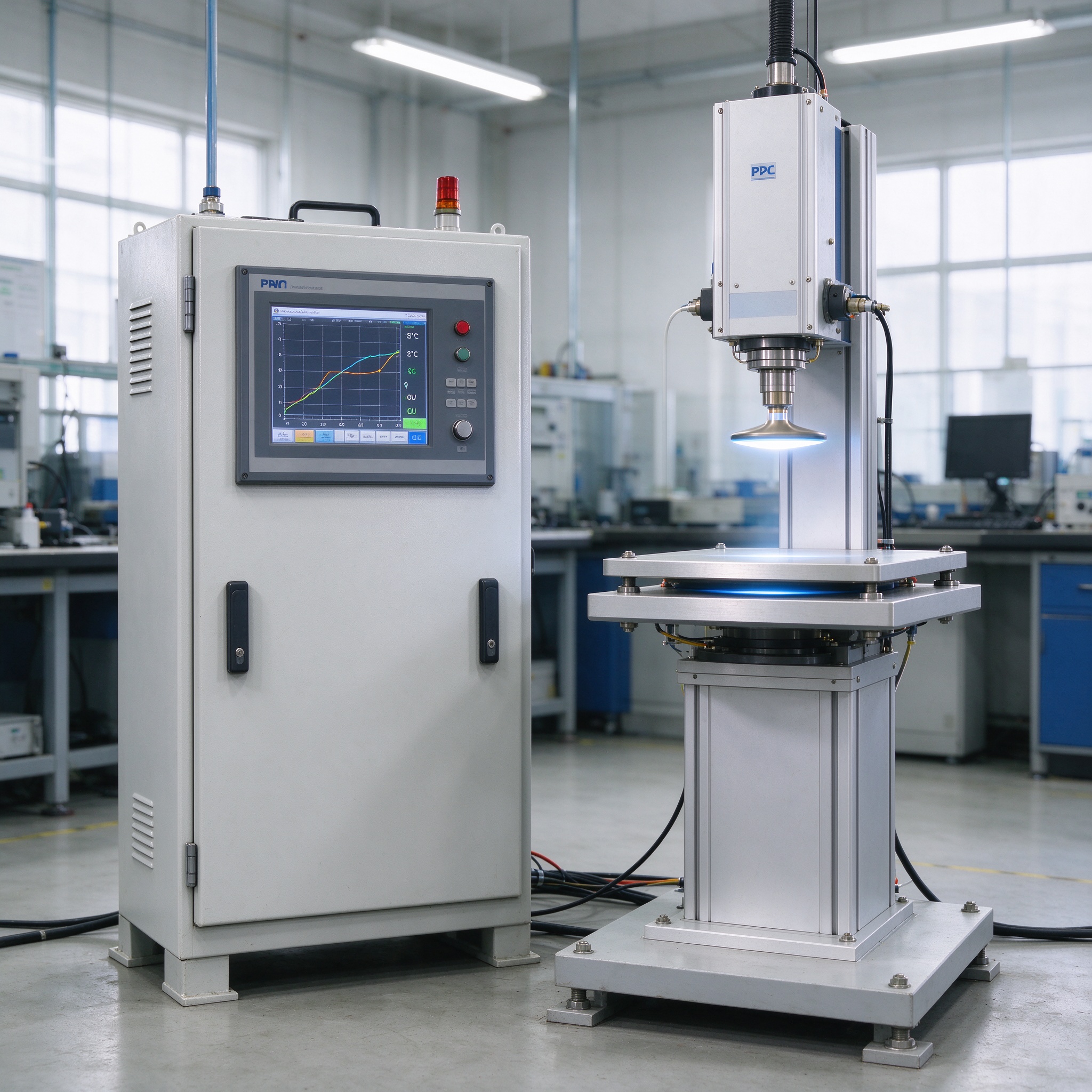
In practice, a magnetic levitation controller reads the gap from a position sensor, computes the error against the target gap, and drives the coil current from the PID output. The tuning gains decide how fast the system corrects, how much it overshoots, and how much margin remains before instability, which is why two systems with the same PID label can behave completely differently.
The Three Terms and What Each One Does
The proportional term reacts to how far the payload is from the target gap. Too little proportional gain and the system is sluggish, drifting under load; too much and it oscillates. The integral term accumulates error over time and removes the steady-state offset that proportional-only control leaves, which matters when the payload’s weight or the coil’s temperature changes slowly.
The derivative term reacts to how fast the gap is changing, damping the motion and letting the system use higher proportional gain without ringing. The balance between the three is the tuning, and the correct balance changes with payload mass, gap and coil characteristics, so a fixed tuning that works for one product often fails for another.
Why the Plant Model Changes with Your Payload
The control loop can only be tuned against the real system, and the real system changes with every payload. Масса, центр тяжести, зазор, coil temperature and mounting stiffness all shift the plant dynamics. A module tuned for a compact, low-center-of-gravity payload can become marginal or unstable when the payload is taller or heavier.
That is why an off-the-shelf module with fixed tuning is a risk for integration projects. The supplier should either provide a tuning range and a method to adapt it, or validate the tuning against your specific payload. Our approach is to test the module with the customer’s payload geometry before committing the design, because the tuning evidence is what makes the difference between a demo and a product.
Disturbance Rejection: The Real Test of a Levitation System
A levitation system only matters under disturbance. Air movement, vibration from nearby machinery, a light touch and thermal drift all act on the payload, and the control loop has finite correction authority. The practical test of a PID-controlled system is how it behaves when disturbed, not how it floats in still air.
When you evaluate a module, ask for the disturbance test conditions and results: the type and magnitude of disturbance, the settling time and the maximum deviation before recovery. If the supplier cannot state these, the stability claim has no boundary, and every claim without a boundary is a marketing claim.
Stability Margins and the Operating Envelope
Every control system has a stability margin: the distance between the operating point and the point where the loop oscillates or diverges. A system tuned too close to its margin is fragile; one tuned with too much margin is sluggish. The engineering question is what margin the supplier designs for across the payload, gap and temperature envelope.
The operating envelope matters as much as the margin. If the module must run in a hot cabinet, on a moving display or with a payload that shifts its center of gravity, the tuning must hold across that whole envelope. Specify the envelope in your RFQ: temperature range, vibration level, gap range and payload variation, and ask the supplier to confirm the system remains stable across all of it.
Power-Loss Behavior in a PID-Controlled System
A PID-controlled levitation system depends on continuous sensor feedback and coil current, so a power failure is a hard disturbance. The protection logic must detect the loss and execute a safe landing within milliseconds, before the payload falls freely. The detection latency and the landing sequence are design parameters that belong in the specification, not in a footnote.
The power-loss protection interacts with the control loop: the controller has to distinguish a genuine power failure from a transient dip or a sensor glitch, and react differently to each. A well-designed system documents the protection logic, the detection threshold and the test record, so the buyer can verify the behavior rather than assume it.
What to Specify in Your RFQ for a PID-Controlled Module
To get an integrable module rather than a demo, specify the payload mass and geometry, the required gap and its tolerance, the disturbance environment, the stability requirement, the power-loss behavior and the operating envelope. Add the integration interface: connector, control inputs, tuning access and the documentation set.
Then ask for the evidence: tuning validation on your payload, disturbance test records with conditions, stability margin data across the envelope, and the power-loss test. A supplier who returns documents for every line is an engineering partner; one who returns only a quote is a component seller.
Контрольный список аудита поставщика: 6 Documents for PID-Controlled Levitation
Before you commit to a PID control magnetic levitation module, request these six documents. Each one verifies a different part of the stability story:
- 1. Tuning validation report for a payload representative of your product, with test conditions.
- 2. Disturbance test record: disturbance type and magnitude, settling time, max deviation.
- 3. Stability margin data across the specified gap, temperature and payload envelope.
- 4. Power-loss test with detection latency and landing behavior recorded.
- 5. Continuous-operation endurance data at your duty cycle and thermal conditions.
- 6. Integration documentation: интерфейс, control inputs, tuning method and failure codes.
A module with these six documents can be integrated with confidence; a module without them is a prototype priced like a product. Treat missing evidence as the first finding of your own technical audit.
Часто задаваемые вопросы: PID Control Magnetic Levitation
Why is PID control used in magnetic levitation?
Magnetic levitation is open-loop unstable, so it needs continuous active correction. PID control provides the proportional, integral and derivative actions that hold the payload at the target gap and reject disturbances in one compact control structure.
What does tuning do in a magnetic levitation system?
Tuning sets the balance between response speed, overshoot and stability margin. The correct gains depend on the payload mass, зазор, coil temperature and mounting, so tuning must be validated against the actual payload rather than assumed.
Can a fixed PID tuning work for different payloads?
Only within a narrow range. Payload mass and center of gravity change the plant dynamics, so a tuning that works for one payload can be marginal or unstable for another. Specify the payload range and require tuning validation for it.
What happens on power failure in a PID-controlled system?
The protection logic detects the loss and lands the payload safely within milliseconds, under the specified test conditions. Request the power-loss test record with detection latency rather than accepting a zero-damage claim without evidence.
How do I compare two PID-controlled levitation modules?
Compare the test evidence, not the algorithm label: disturbance rejection records with conditions, stability margin across the operating envelope, power-loss behavior and continuous-operation endurance. The documents define what the module actually delivers.
CTA
Integrating a PID control magnetic levitation module and need the tuning validated against your payload? Send us your payload mass, geometry and operating environment, and our engineering team will confirm the tuning, the test records and a sample program for your product.
Refer to the Goodwell Maglev Module overview for the module families and integration options available.